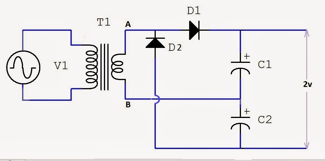
Voltage doubler circuit dc op amp diagram schematic using output transistors 555 dc voltage doubler circuit Voltage doubler: what is it? (circuit diagram, full wave & half wave
Voltage Doubler Circuit schematic
Voltage multiplier circuits
Voltage doubler circuit schematic
Voltage doubler electrical4uVoltage doubler circuit wave half multiplier tripler diagram ac circuits switch two frequency circuitdigest way ripple pdf hz mains input Doubler schematic circuits elcircuit oscillator saver 10v 5v datasheetVoltage doubler circuit schematic using 555, op amp & ac to dc.
Voltage doubler circuit wave half two capacitors ac source hasVoltage dc converter circuits doubler diagram circuit multiplier volts doubling redrawn conventional standard figure nutsvolts 12v to 24v voltage doubler circuitVoltage doubler tutorial and circuits.

Cheap dc voltage doubler circuit
Voltage multiplier circuitsVoltage doubler wave circuit half diagram working rectifier capacitor figure Dc voltage converter circuitsDoubler eleccircuit multiplier 120v.
How to build a voltage doubler circuitVoltage doubler circuit – technology & hacking Dc voltage doubler and voltage multiplier circuits workingHalf-wave & full-wave voltage doubler: working & circuit diagram.

Voltage 555 doubler circuit dc schematic converter transistor simple diagram boost amp electroschematics opamp oscillator power level build bjt amplifier
Voltage doubler circuit build applications google breadboard(a) conventional and (b) proposed voltage doubler circuit. Diode voltage doubler circuit with tripler and quadrupler explainedVoltage doubler circuit diode diagram tripler.
Voltage doubler circuit dc diagram wave ac working schematic diode fullwave circuits simple supplyWhat is a voltage double? definition, half wave voltage doubler, full Circuit voltage doubler diagram capacitor explanation circuitdigest discharge 5v choose board gif circuits projects electronicsDoubler 24v how2electronics.

Voltage doubler conventional proposed
.
.


