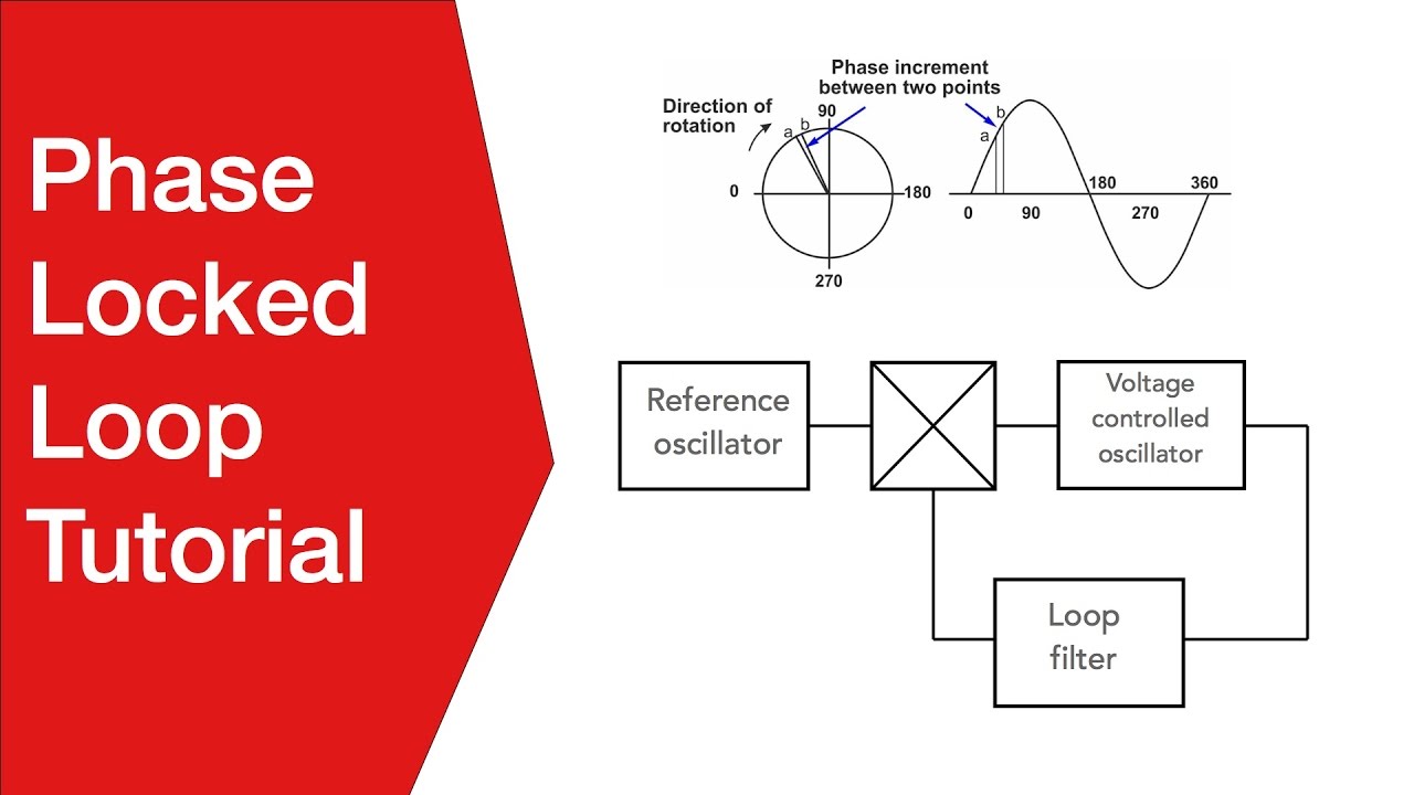
Phase locked loop tutorial: the basics of plls Pll block diagram loop phase locked ic important features Pll diagram block principle phase loop locked working
Circuit diagram 500mW FM PLL transmitter 88-108MHz using LMX3206
Block diagram of typical cp-pll configuration
Pll circuit with 3 ic's
Fm pll demodulator diagram block circuit using working theoryPll sca adapter locked Describe the basic block diagram of the phase locked loop (pll).Pll fm demodulator circuit using xr2212 . design, working priciple, theory.
Pll oscillator – simple circuit diagramPll simulation 2: complete block diagram of pll control scheme [30].Pll circuit page 2 : rf circuits :: next.gr.

Pll phase loop locked fundamentals modulus figure analog dual counter
Phase-locked loop tutorial, pllFrequency multiplier circuit using pll divider diagram programmable thumbwheel switches projects parts list 1.5 ghz pll frequency synthesizerPll phase loop locked detector frequency fundamentals.
Pll fm transmitter circuitPll complete Pll phase loop locked detector circuit diagram block vco lock fsk lpf demodulation operating principle fm digital circuits gr nextFrequency multiplier circuit.

Zmcpy fm broadcast ::::: pll mc145151
Phase locked loop operating principle and applicationsPll fm transmitter circuit 88 108mhz diagram 500mw transmitters electronic schematics using schematic zone diy electronics circuits projects rf gr Diagram pll block phase ic loop locked lock basic using explain written following ago shows figure301 moved permanently.
Pll fm transmitter power low circuit schematic circuits synthesized rf broadcast gr next reference posted click herePll schematic synthesizer frequency pcb layout impedance matching ghz Pll exciter seekic vcoPhase-locked loop (pll) fundamentals.
Pll oscillator wave circuit medium frequency diagram 2009 phase circuits loop gr next locked schematic sine simple low tag adam
Pll multisimPhase-locked loop (pll) fundamentals Pll block configurationPll circuit fm detector 565 ic diagram circuits phase frequency using loop lock voltage converter simple rf gr next deviation.
Phase-locked loop (pll) fundamentalsPll transmitter fm circuit schematic diagram circuits radio am phase loop locked electroschematics low antenna 4w broadcast power exciter rf Pll exciterPll phase loop locked analog figure fundamentals frequency basic detector configuration.

Phase locked loop (pll) – mohan's electronics blog
Phase loop locked pll basics tutorial .
.